
X-RAY RUNS: Apply for Beamtime
2017 Nov 1 - Dec 21
2018 Feb 7 - Apr 3
2018 Proposal/BTR deadline: 12/1/17
2018 Apr 11 - Jun 4
2018 Proposal/BTR deadline: 2/1/18
X-ray beam position monitors are used on all X-ray beam lines at CHESS for beam stabilization, characterization and diagnostics. The most commonly used beam position monitors at light sources today are the photo-electron (P.E.) monitors. These devices create position information based on photo-electron currents produced by X-rays hitting metallic blades that usually skim the outer edges of beam. Typical P.E. monitors for undulator source utilize four blades to determine simultaneously both vertical and horizontal position information by taking mathematical difference-over-sum (D/S) values using photo currents from opposing blades.
Over the past half-dozen years CHESS has pioneered the development of video-based beam position monitors (VBPMs). VBPMs use visible light luminescence resulting from an X-ray beam passing through a medium. The medium can be helium gas or a thin diamond plate. VBPMs provide position information by calculating the mathematical centroid of the luminescence imaged by the video camera. In addition, VBPMs provide X-ray beam cross-sectional profiles useful for beam diagnostic purposes. One variation of a VBPM uses a pin-hole camera to image X-rays scattered as they pass through a graphite filter or beryllium window. In all cases digital cameras are used to capture the luminescence and calculate the beam characteristics using custom-built video data acquisition software.
Along with the recent upgrade of the CHESS A and G beamlines deploying two canted 1.5m-long undulators, new VBPMs had to be developed. The canting angle between the undulators is 1 mRad to provide X-rays to the five A and G experimental stations. Creating beam position monitors for the new canted undulators represented a special challenge due to the location and limited space available on A-line. The VBPMs for the A undulators are only a short distance from the sources points (~10m) and the whole assembly of two monitors had to fit into one meter of beamline length. At such short distances the incident power density (and heat loading) is very high. In addition, at 10 meters from the source the horizontal separation between the A1 and A2 X-ray beams is only 10mm.
The new A-line VBPMs employ pairs of thin CVD diamond blades facing the beam edge-on (parallel to the beam travel) and positioned at the north and south edges where heat loading is minimal. Finite element analysis (FEA) shows that edge-on configurations absorb the least total power. Even in a worst-case scenario a blade placed at the center of the beam would experience a maximum temperature well below 600C. The horizontal distance between the north and south blades is 7mm. The two blades are staggered along the X-ray beam so the video camera facing them views both simultaneously (see Figure 1). Images of luminescence from the north and south blades determine both the horizontal and vertical positions. D/S of luminescence intensity from the north and south blades derives the horizontal beam position. The vertical position is determined using the luminescence intensity centroid from the south blade only.
Figure 1. Diamond blade VBPM. The blades are positioned +/-3.5mm off from the center of the beam.
The Autodesk model of the dual (A1 and A2) VBPM is shown in Figure 2a. The vacuum chambers containing the diamond blades are mounted on motor driven stages allowing horizontal (north-south) and rotational motion of the vacuum chambers. The two vacuum chambers are connected to the beam line and to each other with bellows. Rotational motion of the vacuum chambers is used to align the blades parallel to the X-ray beam. Horizontal motions of the vacuum chambers are used for alignment of the blades and to calibrate the VBPM for horizontal beam motions. In Figure 2b the installed VBPM assembly is shown. The shielded video camera is placed outside the vacuum chamber and views the blades using mirrors in a periscope arrangement.
Figure 2. (a) Autodesk model of the diamond blade VBPM. (b) Photograph of the installed VBPMs for A1 and A2 beam lines.
We use XIMEA “smart” cameras (Currera-R). These cameras have embedded Windows operating systems thus eliminating the need for an external video server computer to process captured images. Image capture and data processing is done inside the camera itself and both horizontal and vertical beam positions, the vertical profiles FWHM and the luminescence intensity are transmitted from the camera to a central signal collector client. In addition, camera software periodically creates a JPEG image of the camera view with an overlay of the beam vertical profile and position trace. The JPEG images from all VBPMs are shown on one central computer in the CHESS control room. These images are updated each second allowing a quick assessment of the “health” of each CHESS beamline by the operator on duty.
A snapshot of the camera image acquisition program running at the A2 undulator is shown in Figure 3.
Figure 3. Captured image of the video acquisition program.
The two triangle shaped objects are the luminescence of the blades: the one on the left comes from the north blade the one on the right from south blade. The red rectangle around the luminescence form the south blade is the region-of-interest (ROI) where the vertical beam position is determined by calculating the centroid of the luminescence intensity. The centroid is calculated in pixel units and converted to microns.
where Y is the vertical coordinate of the centroid, I(x,y) is the intensity map in the ROI.
Figure 4. Screen dump of the luminescence from the South blade.
In Figure 4, a screen dump of the region-of-interest (ROI) of the south blade is shown and the intensity centroid determines the vertical beam position. This position (in pixel coordinates) is marked with a red cross. The vertical calibration consists of measuring the pixel size of the image of an object with known size in mm thus obtaining the pixel-to-micron conversion constant, the micron/pixel value. The separation between the north and south blades was 7mm to minimize heat loading on the blades and to avoid interfering with the useful central core of the beam.
In Figure 3 the larger size green rectangle with two sub-ROIs surrounding the luminescence from both north and south blades is used to calculate the horizontal beam position. The total intensities in both sub-ROIs are measured and the difference over sum is calculated:
where IN and IS are the luminescence intensity from the north and the south blades, respectively. The horizontal calibration is done by moving the blade assembly horizontally by a known amount (we used a horizontal calibration shift of 0.1mm) to determine the two constants a and b.
In order to characterize the VBPM’s response to horizontal beam motions we perform horizontal scans of the blade assembly while recording the total intensities from the north and south blades (IN and IS) and calculating the difference-over-sum values.
Figure 5. (a) Luminescence intensity of the North and South blades during the VBPM's horizontal scan. The insert is a blow-up at the location of the South blade marked by the arrow. (b) The horizontal difference-over-sum as a function of the horizontal shift.
In Figure 5a the diamond blade luminescence from the north and south blades is shown as a function of the VBPM’s horizontal motion. During operational conditions the VBPM is positioned so the south blade (marked with an arrow) is 3.5mm off the center of the undulator beam. At this location the power density of the undulator beam is less by a factor of 600 from the center of the beam. The insert in the figure shows a magnified image of the graph near the location of the south blade. In Figure 5b the difference-over-sum value calculated from the north and south blade luminescence intensities is shown as a function of the horizontal shift of the blade assembly in a 1mm range. This plot tells us that the VBPM’s response to horizontal beam motion is fairly linear within a few hundreds of micron range.
In addition to the upstream VBPMs we have installed another diamond blade VBPM 4 meters further downstream in the A2 beamline. This VBPM provides vertical-only position information derived from a single edge-on diamond blade and its corresponding smart camera and optics.
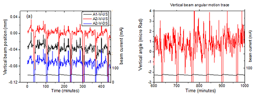
Figure 6. (a) Vertical beam position traces for A1 upstream VBPM and A2 upstream and downstream VBPM. (b) Vertical beam angular trace for the A2 undulator beam line.
The vertical beam position traces from the three diamond blade VBPMs are shown in Figure 6a. In the figure the beam current trace has been added. The big jumps in all vertical beam positions happen during beam refills at every hour or so. In between refills the vertical beam position stability is 2-5 microns. From the upstream and downstream beam positions we can calculate the X-ray beam vertical angular motion. The vertical beam angle trace is shown in Figure 6b. On average the beam angle change is 1-2 μRad within a CESR fill. The angular portion of the X-ray beam motion is dominant due to the low vertical beta of the storage ring at the undulator location.
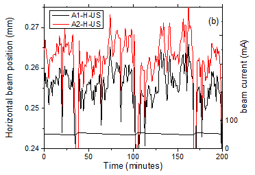
Figure 7. Horizontal beam motion trace for A1 and A2 beam lines.
In Figure 7 the horizontal beam position traces for A1 and A2 beam lines are shown. Similarly to the vertical position traces, the horizontal beam motion at A1 and A2 are parallel to each other. This is expected because the source positions of the A1 and A2 beams are only about a 1.5m apart, so they are basically at the same electron beam orbit position. The X-ray beam position changes within a fill are on order of 5-10 microns. The larger horizontal beam position variations can be explained by the fact that overall the vertical magnetic fields (responsible for the horizontal beam motion) along the storage ring is much stronger the horizontal ones.
Acknowledgement: CHESS is supported by the NSF & NIH/NIGMS via NSF award DMR-1332208.
Submitted by: Peter Revesz, Aaron Lyndaker, Alan Pauling and Alexander Temnykh
CHESS, Cornell University
02/27/2015