
X-RAY RUNS: Apply for Beamtime
2017 Nov 1 - Dec 21
2018 Feb 7 - Apr 3
2018 Proposal/BTR deadline: 12/1/17
2018 Apr 11 - Jun 4
2018 Proposal/BTR deadline: 2/1/18
At CHESS, the X-ray position monitoring and position stabilization feedback by CESR is fully realized using CHESS’ video beam position monitors (VBPMs). Throughout the years, we have developed five different types of VBPMs. These VBPMs are schematically shown in Figure 1 with images created by these devices. All VBPMs provide position information with submicron precision, in addition to visual information about the X-ray cross-sectional shape. The data delivered from the VBPMs are normally updated in each second. This frequency of data delivery is appropriate for the position feedback system and our signal-archiving timing intervals.
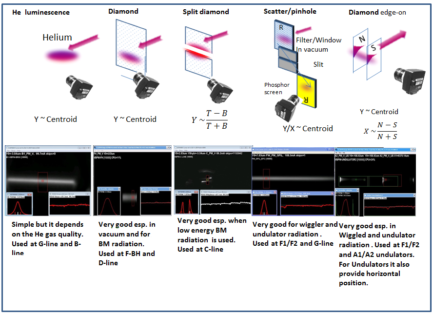
Figure 1: Summary of VBPMs at CHESS.
- VBPMs based on helium gas luminescence are used on beam lines where white beam passes through helium-filled sections. The helium luminescence is observed through a viewport on the side of the beam pipe. One downside of this method is that the intensity helium luminescence strongly depends on the purity of the helium.
- Hard bend radiation passing through a thin CVD diamond sheet results in intense luminescence of the diamond as the footprint of the beam passes though the diamond. Best used in vacuum conditions - over time, contamination may be deposited on the diamond surface in helium-filled systems. (F-HB and D-line)
- A variation of the previous VBPM is the split diamond VBPM. In this version, the center core of the HB radiation is unobstructed and the X-rays pass through between two diamond plates. The advantage of this design is that beam is mostly unaffected by the VBPM system. The position information is derived from the difference-over-sum of the top and bottom diamond luminescence. This type is used at C-line.
- Slit or pinhole VBPM design: when white X-rays pass through a graphite filter or a Be window, X-rays will forward scatter from the footprint of the beam. These are mostly high energy X-rays that easily pass through a viewport. The X-rays are then detected with a pin-hole arrangement as the scattered X-rays create an image on a fluorescent screen. Used at G and F-lines.
- The newest design is the edge-on diamond VBPM. Here the diamond plate(s) are inserted parallel to the beam’s propagation. In this configuration the heat load on the diamond is very low due to the small cross section of the diamond facing the X-ray beam. The diamond plates can be placed at both edges of an undulator beam. This VBPM will provide vertical position information from the centroid and horizontal position information from the difference-over-the- sum of the two plate’s luminescence. This design has been implemented at A1 and A2 undulator beam lines, and a new installation of this type is now found in the C-line upstream VBPM (which replaces the old C-line PE monitor), and at F2/F1 wiggler beam lines, replacing the helium-based VBPM.
- F1/F2 Edge-on VBPM
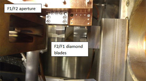
Figure 2: F1/F2 mono box with edge-on diamond VBPM.
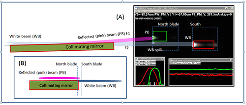
Figure 3: F1/F2 Edge-on VBPM.
The old F1/F2 VBPM used helium fluorescence. The VBPM had two problems: low intensity due to dependence on gas humidity and purity, and degradation of fluorescence due to helium contamination. Additionally, as a result of the wider spread of the helium luminescence, the signals from F1 and F2 were difficult to separate.
The new edge-on diamond VBPM was installed upstream of the aperture (see Figure 2). The diamond plates have been clamped to a Cu holder that was fixed to the aperture providing cooling by conduction. This VBPM has to deal with two beams: F2, the direct white beam from the F-line wiggler (south blade), and, the F1 beam, the mirror reflected beam (north beam blade). The horizontal separation between the north (F1) and the south blades (F2) was 7 mm. In Figure 3, on the left side, the schematics of some beam components and X-ray beam path is shown. The north blade shows the luminescence from the mirror reflected part of the beam (plus some spill-over), whereas the south blade displays the luminescence from the direct white beam. In part B of Figure 3, the locations on the blades are shown as viewed from the downstream direction.
On the right side of Figure 3 (part A) the image obtained by the VBPM data acquisition program is shown. The F1/F2 beam and the spillover luminescence are well separated. This screenshot also shows the two ROIs (red and green squares) where the position centroids are calculated. Note that the spillover portion of the F1 beam is well-separated from the F1 beam. This separation was not possible when helium luminescence VBPM was used.
After six months of use, the new VBPM system at F-line has shown small amounts of contamination build-up on the blades. The build-up of this contamination on the blades’ surface is a very slow process and it does not have a measurable impact on the VBPM’s performance.
- The New Edge-on VBPM at C-line
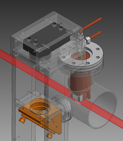
Figure 4: C-line Edge-on VBPM.
We have replaced the old PE-type position monitor with and edge-on type diamond VBPM.
In figure 4, the design concept of the C-line VBPM is shown. The diamond blade is clamped to a water cooled Cu holder near the center of the beam pipe. In the Figure 4 the X-ray beam is shown as a red band intercepting the edge-on diamond blade. The diamond luminescence is viewed through a viewport from the side through the mirror mount and a Currera (by XIMEA) camera. The camera has an embedded XP operational system that carries out all image acquisition and processing and data transmission functions.
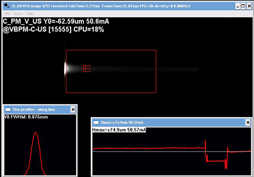
Figure 5: Screen dump from the edge-on diamond C-line VBPM.
The screen dump from the C-line VBPM is shown in Figure 5. Here the beam (coming from left-to-right) hits the diamond blade edge resulting intensive luminescence. The beam position is determined as the pixel intensity centroid from the luminescence map inside of the ROI (shown as a red rectangle). The insert on the left shows the vertical profile of the beam; on the left, the beam position trace is shown.
- G-line Pinhole camera VBPM
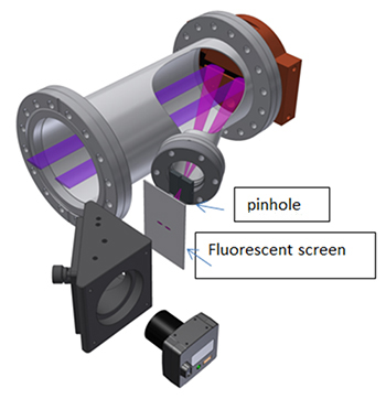
Figure 6: Concept of the G-line pinhole VBPM.
At the original F-line VBPM we used a horizontal heavy-met slit placed at the viewport. The forward scattered high energy X-rays easily penetrate through the viewport. The slit created an image in form of a line of the beam on the fluorescent screen coming from the beam’s footprint on the Be window. Having two undulator beams we realized that using a pinhole instead of a slit we can obtain the images of the footprint for both (G1 and G2) beams allowing us to independently measure both vertical and horizontal beam positions for G1 and G2 beams. Note the fluorescent screen is parallel to the Be window therefore the pinhole demagnification is constant along the image for any scattered X-rays. The demagnification factor of the pinhole was measured by introducing a small (100um) vertical displacement of the slit and measuring the resulting change of the vertical position of the image. The demagnification factor basically is the ratio of the distances Be-window-to-Pinhole and Pinhole-to-fluorescent screen.
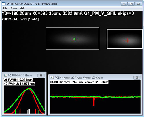
Figure 7: Screen dump from the G-line VBPM showing the G1 and G2 beams.
The screen dump of the G-line pinhole VBPM is shown in figure 7. The vertical (red) and horizontal (green) profiles shown in the left insert (for G1) and the vertical (red) and horizontal (green) beam position traces are shown in the right. To avoid clutter in these displays profiles and traces only one beam is shown as selected by the operator (the selection is shown with thicker ROI, in figure 7, G1 is the selected beam. The centroid program reports to CHESS’s and CESR signal data control systems for both beams regardless of the display selection.
- SUMMARY
- Replaced the antiquated C-line PE beam position with an edge-on VBPM.
- The G-line scatter VBPM now employs a pinhole instead of a slit. This allows us to have both horizontal and vertical beam position.
- We installed diamond blades in edge-on configuration in F1/F2 mono-box. This way we use the more intensive and spatially better defined diamond luminescence instead of the helium glow. In addition, the new diamond VBPM allows a better separation between the reflected beam from the spillover.
Submitted by: Peter Revesz, Zach Brown, Arthur Campello, John Conrad and Aaron Lyndaker, CHESS, Cornell University
03/03/2016