
X-RAY RUNS: Apply for Beamtime
2017 Nov 1 - Dec 21
2018 Feb 7 - Apr 3
2018 Proposal/BTR deadline: 12/1/17
2018 Apr 11 - Jun 4
2018 Proposal/BTR deadline: 2/1/18
Challenges in aerospace engineering, such as the design of rocket nozzles and atmospheric re-entry vehicles, require lightweight materials which demonstrate high strength at extreme temperatures. Carbon-fibre-reinforced-carbon (aka “carbon-carbon” or “C/C”) is a leading, tough, low-density material that has been extensively used for these applications. Despite its many advantages, C/C does suffer from being susceptible to oxidization, and must therefore be coated with some protective layer prior to use. The residual and thermally-induced strains between C/C and its protective coatings must be understood in order to engineer safer, lighter vehicles.
As reported in a new article[1], researchers from the Australian Dept. of Defense (DST Group, Aerospace Division), lead by first author John Thornton, have used high energy x-rays at CHESS to map depth-dependent phase and strain in several samples of C/C which have been coated with sodium silicate glass and silicon carbide. They investigated both “pristine” samples, as well as samples which had been blasted using an oxy-acetylene torch to simulate operating conditions. Mismatch in thermal contraction of coating and C/C results in through-thickness cracks of the SiC layer which must be filled using sodium silicate glass. The degree of oxidation of the coating was shown to effectively tune this strain mismatch, as was the degree to which the interface is compositionally graded. The detailed understanding of the strains present in each phase, as a function of depth, allowed Thornton and colleagues to propose ways to improve oxidation resistance in the future, by introducing a composition-graded buffer layer of graphite between the C/C and the SiC. This should reduce the tensile strain, and thus also reduce the density of through thickness cracks.
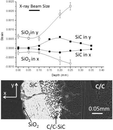
Figure 1: Strains in the cristobalite (SiO2 and open symbols) and SiC (closed symbols) for the heated material. The solid lines fitted to the data points are a visual guide and do not represent the predictions of a model. Cross-section included for comparison with microstructure. (From Ref [1])
Reference:
[1] John Thornton, Darren Dale, Jacob Ruff, and Chris Wood, “Phase and strain mapping of a protective coating on carbon–carbon,” Surface and Coatings Technology, Volume 287, (2016).
Submitted by: Jacob Ruff, CHESS, Cornell University
02/04/2016