
X-RAY RUNS: Apply for Beamtime
2017 Nov 1 - Dec 21
2018 Feb 7 - Apr 3
2018 Proposal/BTR deadline: 12/1/17
2018 Apr 11 - Jun 4
2018 Proposal/BTR deadline: 2/1/18
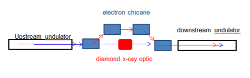
Latest generation free-electron lasers (FEL) generate x-ray radiation by amplifying shot noise produced as electron pass through a very long undulator. The x-ray pulses have many longitudinal modes, so energy fluctuates over a finite bandwidth. Longitudinally coherent x-ray pulses can be made by sending longitudinally coherent radiation along with electrons through the undulator. This so-called “self-seeding” is done between long undulator sections by separating electron from x-ray beams using a magnetic chicane, monochromatizing the x-rays, and finally recombining beams as indicated in Figure 1.
Geloni [1] proposed monochromatization by Forward Bragg Diffraction (FBD). This delays the narrowband x-ray pulse by femtoseconds, and produces small transverse displacement of the X-ray beam. To optimize FEL performance it is important to compensate for these displacements, so scientists from SwissFEL worked with CHESS scientist Ken Finkelstein to learn how to measure subtle transverse displacements on the ten micron scale. The experiment is shown schematically in Figure 2.
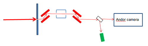
A specially designed x-ray camera, used for topography at the C1 station, was used to image beams transmitted by near perfect diamond crystal plates of thickness 600μm. The incident beam was prepared with angle and energy spread closely matching the Darwin acceptance of the diamond (400) reflection, while upstream slits define beam spatial size to 10μm in the diffraction plane. The x-ray camera resolves about 3μm features, and images of the transmitted beam in Figure 3 (below) show effects of “forward Bragg diffraction” consistent with diffraction theory of Lindberg & Shvyd’ko [2].
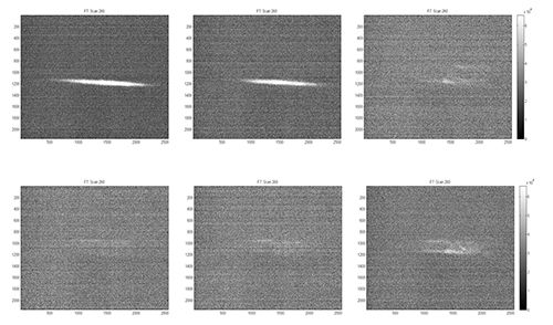
Figure 3: Images of the x-ray beam transmitted through a diamond plate as it is rocked through the (400) Bragg reflection (left to right first row, followed by second row). The image sequence begins with crystal set below the Bragg angle, progresses through angles where beam is primarily diffracted to the green detector in Figure 2, and finally diffracted mainly in the forward direction. Vertical beam shape changes close to expectations, with total width changing from 10 to about 40μm. The signal is weak because a bend magnet source is not well matched to the reflection.
This first experiment taught us how to do the measurements, and gave results consistent with simulations. We will continue the work in September 2015, using the CHESS setup at an undulator beamline of the Swiss Light Source (SLS).
References:
[1] G.Geloni, V. Kocharyan and E. Saldin DESY report 10-053 (2010).
[2] R. R. Lindberg and Y. V. Shvyd’ko, Phys. Rev. ST Accel. Beams 15, 050706 (2012).
Submitted by:
Ken Finkelstein, CHESS, Cornell University
09/10/2015