
X-RAY RUNS: Apply for Beamtime
2017 Nov 1 - Dec 21
2018 Feb 7 - Apr 3
2018 Proposal/BTR deadline: 12/1/17
2018 Apr 11 - Jun 4
2018 Proposal/BTR deadline: 2/1/18
Many ancient inscriptions on stones have been worn and weathered, and the original text is no longer visible. Scanning X-ray fluorescence (SXRF) imaging of chemical tracing elements on epigraphy has been used to significantly improve the legibility of heavily weathered and worn stone surfaces. The origins of the trace elements observed by SXRF in inscribed regions are unclear, but are speculated being derived from the tools and paints used in the original inscriptions. Although SXRF is effective for naturally worn surfaces, the measurement has also been complicated by object surface curvature or relief, such as incised letters. When a pencil beam of hard X-rays, normally with width of 1 μm – 1 mm, penetrates into an object, part of fluorescence excited between object surface and about 500 μm underneath can penetrate backwards out of the object and detected by X-ray fluorescence detector. Object surface curvature changes the path-length inside object of these “escaping” fluorescence therefore changes the fraction of how much fluorescence being absorbed by the object itself. Accurate mapping of SXRF of the object requires a method to correct the modulations caused by arbitrary geometries of object surface.
CHESS users, former Cornell graduate student, Ethan C. Geil and his mentor, Prof. Robert E. Thorne, have introduced an easy-to-implement method to correct the modulation of X-ray fluorescence intensity by surface orientation to incident beam. Experiment with a 1000 BC Middle East gypsum tablet was conducted at CHESS F3 beamline. The mapping of the surface orientation using their method reveals the original inscription with surprisingly clearness and accuracy (fig. a & b), and corrected fluorescence mapping reveals higher Pb and Ti concentration in the incised areas. The results concluded the significant improvement of SXRF imaging on non-flat surface objects. Details can be found in the paper: http://journals.iucr.org/s/issues/2014/06/00/hf5269/.
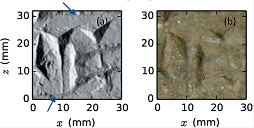
Figure (a): Surface angle map using correction algorithm introduced by E.C. Geil and R.E. Thorne. (b): photograph of scanned area, adjusted to enhance contrast and brightness. The surface angle map gives a clear and detailed picture of surface relief, including the fine horizontal rulings (marked by arrows).
Submitted by: Rong Huang, CHESS, Cornell University
02/03/2015